




The 5-minute trick that saves hundreds in ruined laser material
If you’ve ever loaded an expensive sheet of custom-milled walnut, anodized aluminum, or imported cast acrylic into your laser cutter, held your breath, and hit “Start” based on a vague guess or a forum post from 2021, you know the dread.
Two minutes later, you’re either looking at a ghostly, unreadable smudge that barely kissed the surface or a charred, smoking trench that smells like regret. You tweak a slider, waste another piece of stock, adjust the air assist, and repeat. Before you know it, you’ve burned through half your material just trying to find a baseline.
In the maker space, time is currency, and substrate material is getting more expensive by the month. Whether you run a diode laser in a garage setup or a commercial CO2 machine, guessing your power and speed parameters is a silent profit killer.
The antidote? The material test card.
Here is why designing and running a parameter test grid on every new batch of material is the single best workflow upgrade you can adopt, and how to build one that saves you time, material, and sanity.
What Is a material test card?
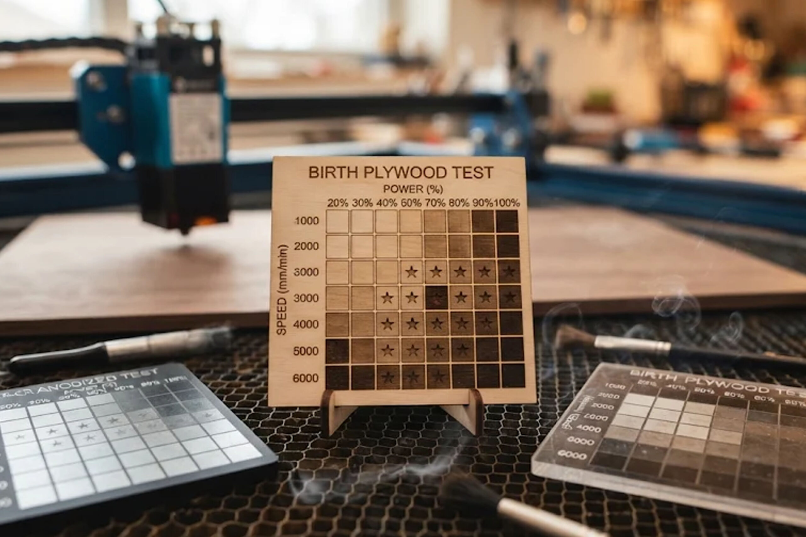
A material test card (often called a speed-and-power matrix) is a grid of small cells—usually etched or cut into a scrap corner of your substrate. Each individual cell runs on a distinct, calculated combination of two primary variables: Laser Power (varying across the X-axis columns) and Speed (varying down the Y-axis rows).
Instead of running twenty separate jobs, a single test card lets you map out an entire matrix of parameters simultaneously. When the job finishes, you have a physical gradient of results right in front of you. You simply inspect the grid, find the square that yields the cleanest contrast or the crispest cut, and read the exact numbers engraved right beside or beneath it.
Why guessing fails (even with “standard” settings)
Makers love to share parameter charts online, and they are a great starting point. But relying on them blindly ignores the chaotic reality of manufacturing variables:
- Batch-to-Batch Variance: Two sheets of “3mm Basswood plywood” bought three months apart can have entirely different core glues, veneer thicknesses, and moisture levels. Glue density dictates how a laser reacts far more than the wood species itself.
- Diode vs. CO2 Peculiarities: A 10W diode laser behaves fundamentally differently from a 40W fiber or a 100W CO2 glass tube. Even two “identical” 20W diode modules can have slight variations in beam profile and optical output power due to manufacturing tolerances.
- Lens Degradation and Focus: A slightly dirty lens or a 0.5mm error in manual focus changes your energy density per square millimeter. A test card forces you to calibrate to your current machine state, not an idealized laboratory baseline.
How to design and run your parameter grid
Modern software suites like LightBurn have built-in material test generators, and free web-based generators can export clean SVGs for platforms like xTool Creative Space or Glowforge. To make your grids as effective as possible, follow this step-by-step workflow:
- Step 1: Establish Your Baseline Boundaries – Don’t test blind. If you know from general experience that a material usually engraves well around 3000 mm/min, set your grid’s speed range to bracket that estimate (e.g., from 2000 to 4000 mm/min). For power, span a safe middle-to-high bracket (e.g., 40% to 80%).
- Step 2: Dedicate a Scrap Corner – Always use a piece of the exact same stock you intend to use for your final project. Place your test grid in a corner where a 50mm x 50mm or 70mm x 70mm square won’t ruin a larger piece layout.
- Step 3: Lock Your Hardware Variables – Before hitting frame preview, lock down everything that affects laser-to-material geometry: Focus height: Re-check your focus pin or electronic autofocus. Air assist: Ensure your compressor or internal pump is set to the exact PSI/level you plan to use for the actual job. Changing air pressure halfway through a project invalidates your test data.
- Step 4: Frame and Run – Run a boundary frame check on your laser bed to ensure the test card stays strictly within your scrap boundaries. Fire the job and watch the first few rows.
Reading the matrix: what to look for
When your laser finishes, look past the aesthetic look of the card and evaluate it analytically:
- The Engraving Test: Look for clean contrast without physical surface distortion. If the wood is deeply pitted or warped, your power is too high or your speed is too slow, causing thermal carbonization. If the text is faint and barely perceptible, you’re under-powered.
- The Cut Test (If applicable): Push gently on the squares from the back. The ideal cut parameter is the one where the square drops out cleanly with a minimal push, showing zero excessive charring on the underside edges. That gives you your maximum speed / minimum power threshold—maximizing efficiency while protecting your honeycomb bed from heavy flashback.
The two-pass pro tip: broad vs. fine grids
If you are working with an entirely unknown exotic material (like a strange synthetic leather or a mystery acrylic), use a two-tier strategy:
- The Discovery Grid: Run a wide-span grid with aggressive gaps in speed and power to find the general “sweet spot” zone.
- The Micro Grid: Once you know the sweet spot is around 50% power and 3000 speed, generate a second, smaller grid tightly clustered around those exact numbers (e.g., 45%–55% power, 2700–3300 speed) to dial in absolute perfection.
Final thoughts
Spending five minutes and a 2×2 inch scrap of material to run a test grid feels like an interruption when you’re eager to start a project. But it is a psychological and financial safety net. By making the test card a mandatory ritual for every new material acquisition, you turn laser crafting from a game of expensive guesswork into a predictable, repeatable science.

Related Posts